Projects / 2026
Three-Roller Ground Intake
A complete FRC ground intake designed in Onshape over two evenings: three belt-driven rollers, a 40:1 chain-driven pivot, and 3D-printed dead-axle roller hubs.
- Team
- FRC 1294 · Pack of Parts
- Tool
- Onshape
- Design time
- Two evenings
- Role
- Lead designer
- Status
- CAD complete
- Date
- Oct 2026
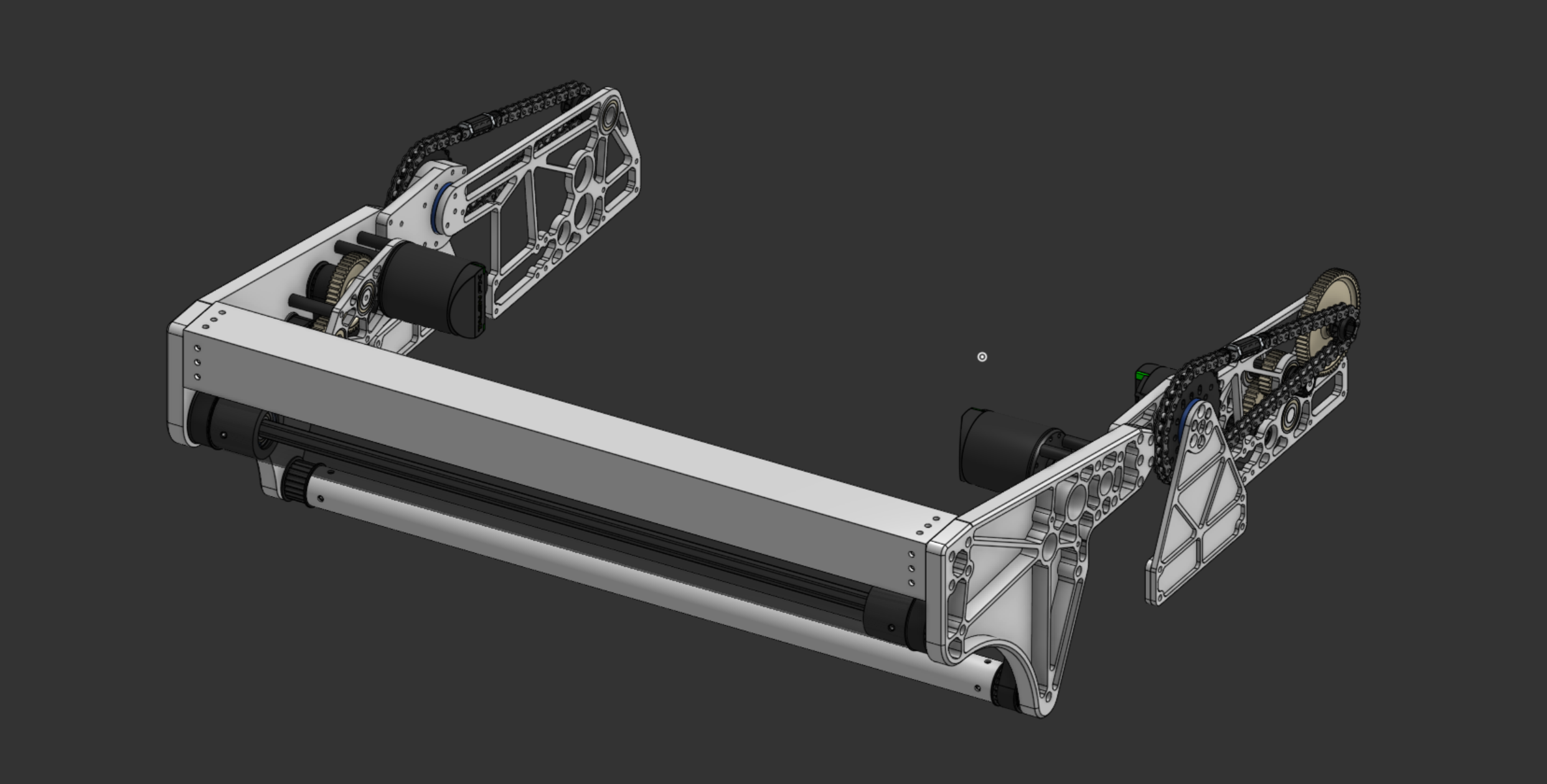
The intake is the robot’s first contact with the game piece. It has to pull a ball off the floor quickly, hand it into the robot cleanly, survive collisions, and fold away when it isn’t deployed. This design covers the complete mechanism — structure, roller drive, pivot, and roller hardware — and was completed in two evenings.
Design goals
- Reliable pickup — control the ball through the entire handoff, not just at first contact.
- Durability — the intake leads the robot into walls, field elements, and other robots.
- Compact stowing — fold flat when not deployed.
- Low weight — mass on a pivoting arm costs deploy speed and motor load.
Design decisions
Three rollers instead of one
Three powered rollers contact the ball in sequence, so it is guided continuously from the floor into the robot instead of depending on a single pinch point.
A crash bar takes the hits
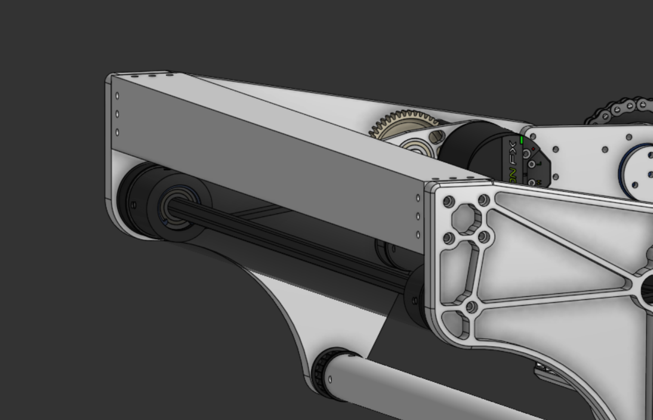
The leading structural member is a 2×2 box tube rather than another polycarbonate roller. The front of the intake is what strikes walls and other robots first; a rigid tube absorbs those impacts, where a thin-walled spinning roller would dent or bend.
Pivot: 40:1 reduction, chain on both sides
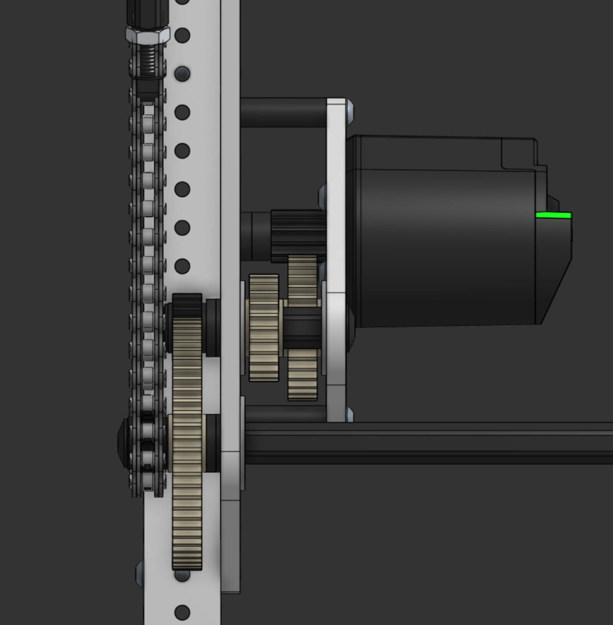
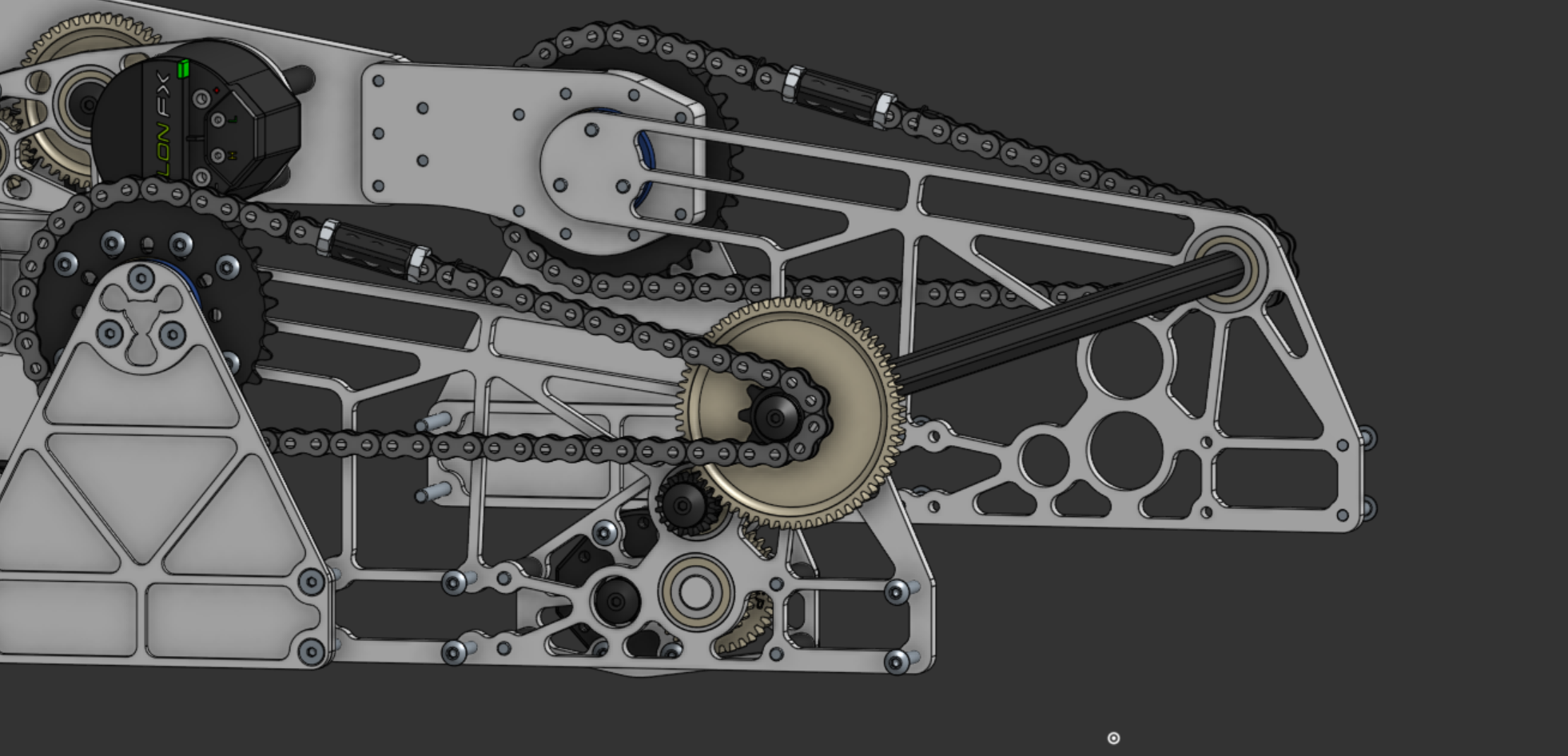
The intake deploys and stows through a 40:1 gearbox. Instead of driving one side and letting the other follow, the gearbox output pulls chain on both sides. Driving both sides keeps the wide intake from twisting under load.
Pocketed side plates
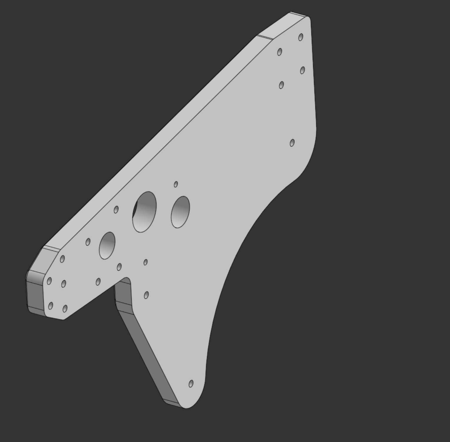
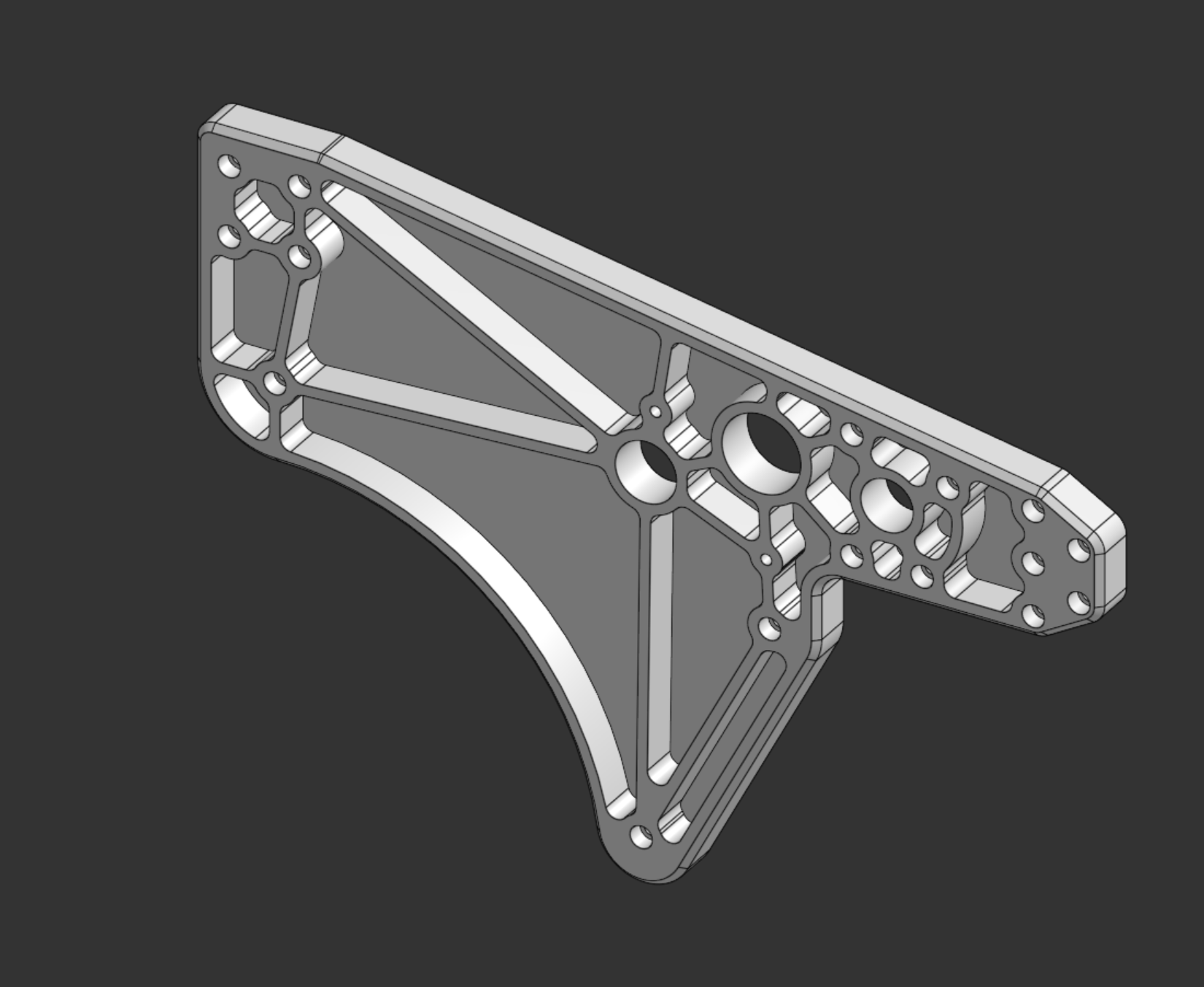
The side plates are pocketed to partial depth rather than cut all the way through, and the bolt holes are recessed so hardware sits below the surface. That leaves one face continuous: the intake stows with a flat profile, the ball rides over a smooth surface with nothing to catch on, and the plate keeps more of its strength than it would with through-cut lightening.
Two motors driving all three rollers
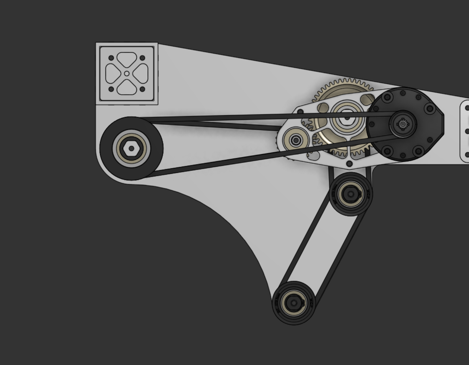
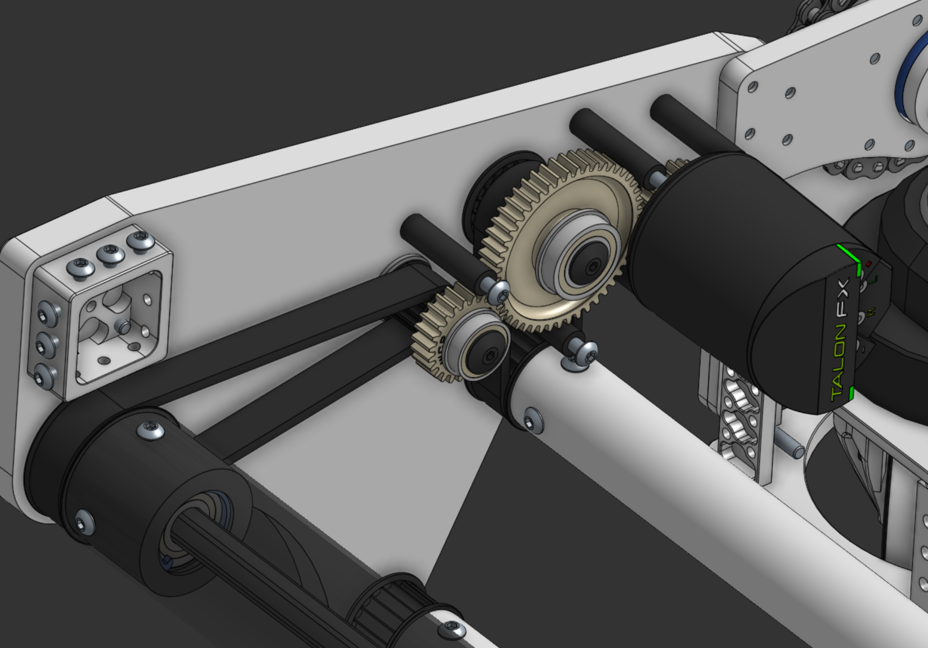
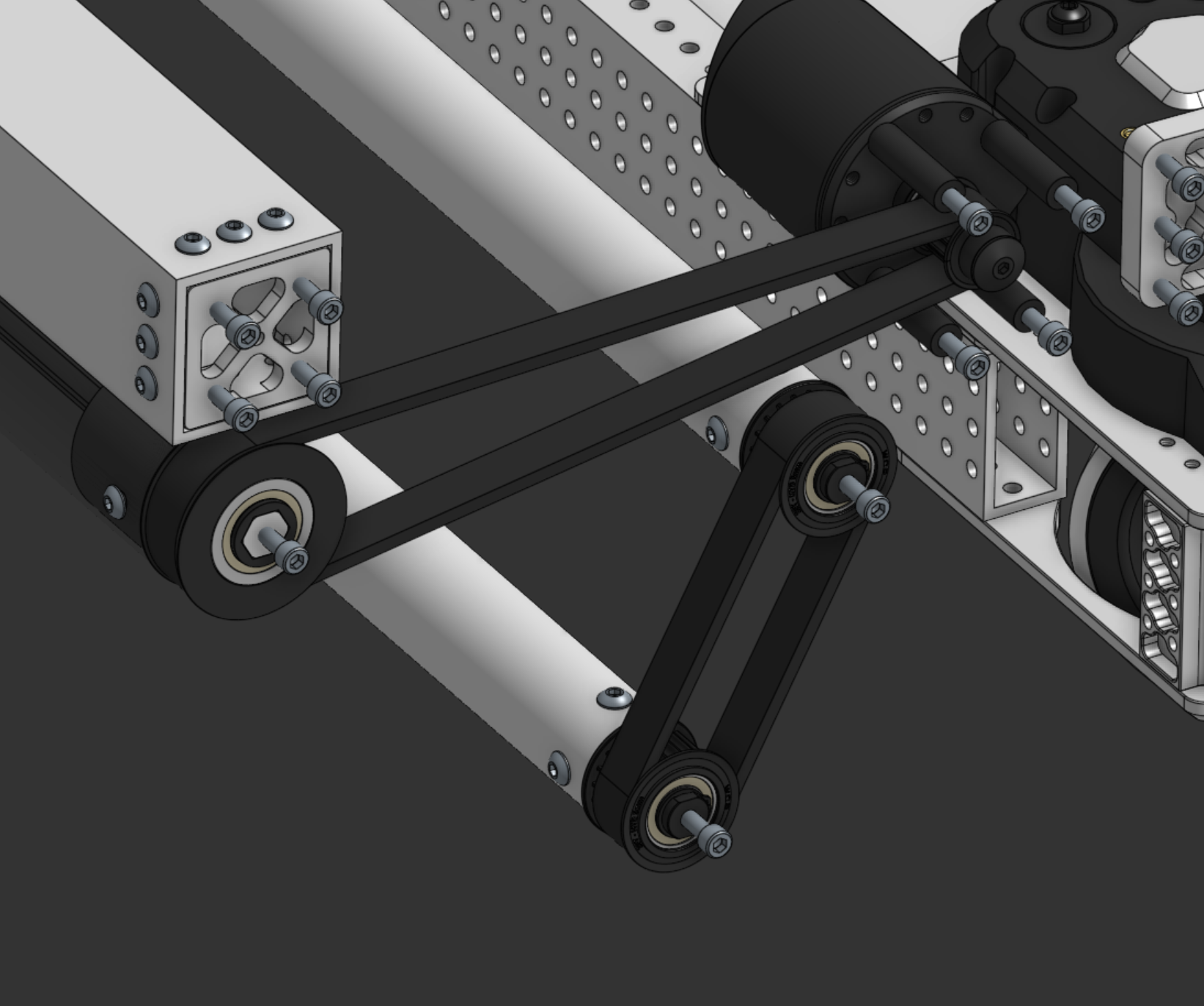
Rather than giving each roller its own motor, an idler gear and a set of belts tie both motors to all three rollers. When a ball loads one roller, the power of both motors is available to push through it, and the rollers stay mechanically synchronized.
Pivoting on a captured bearing
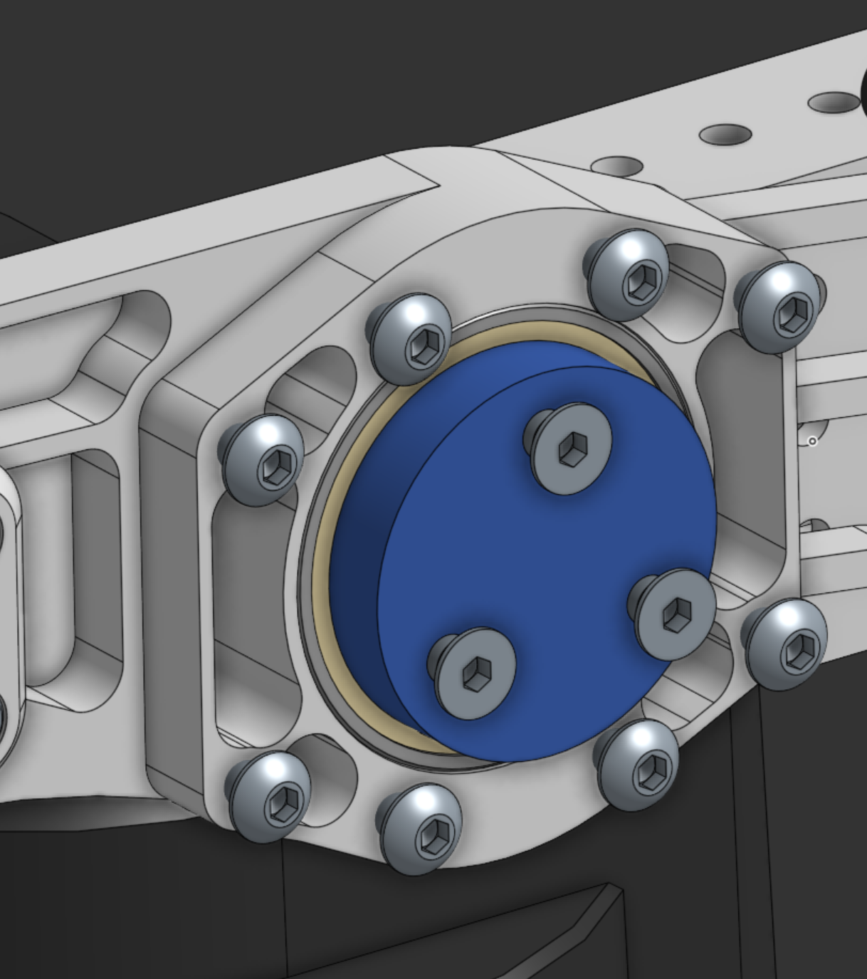
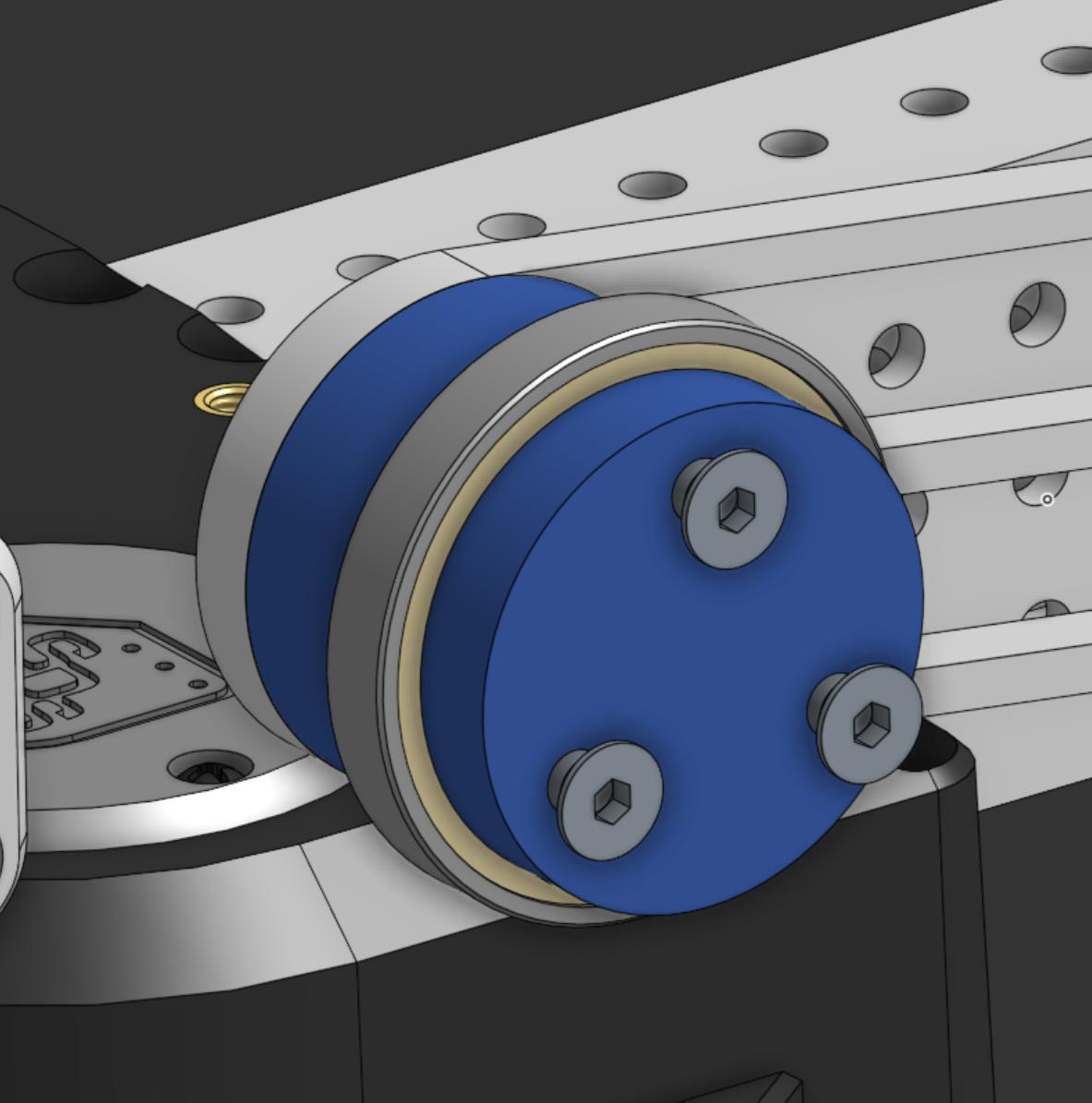
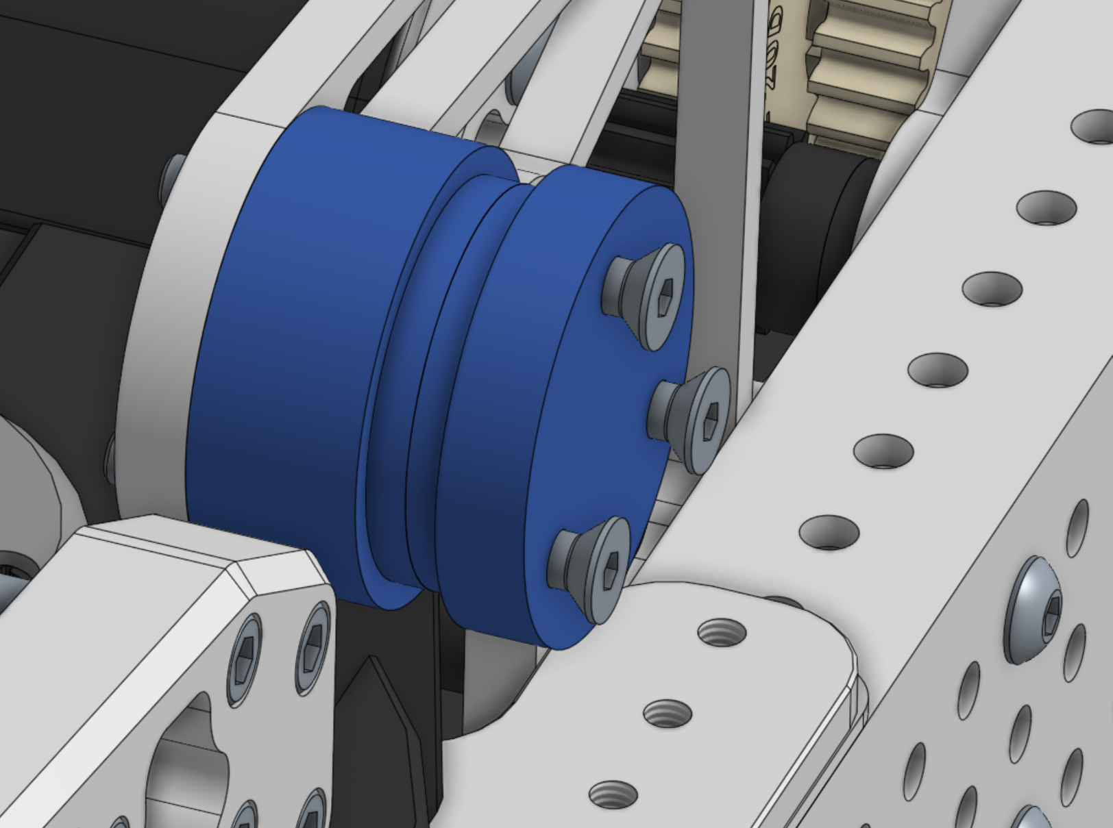
The intake pivots on a bearing captured in a 3D-printed slot (shown in blue), which locates and retains the bearing without additional machined parts.
Main roller: dead axle with printed hubs
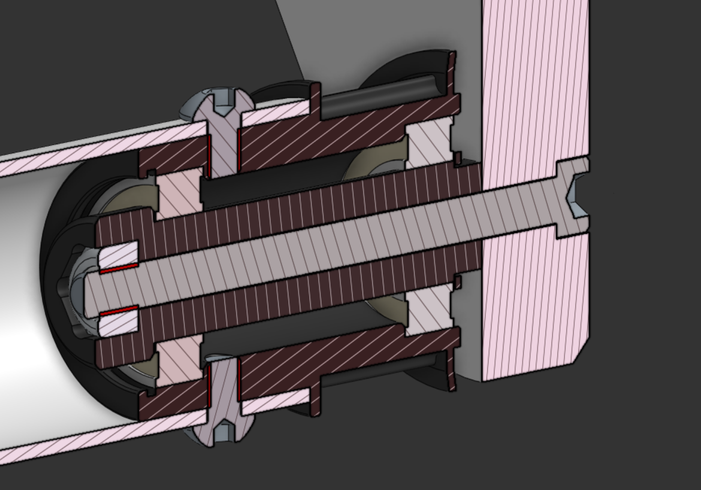
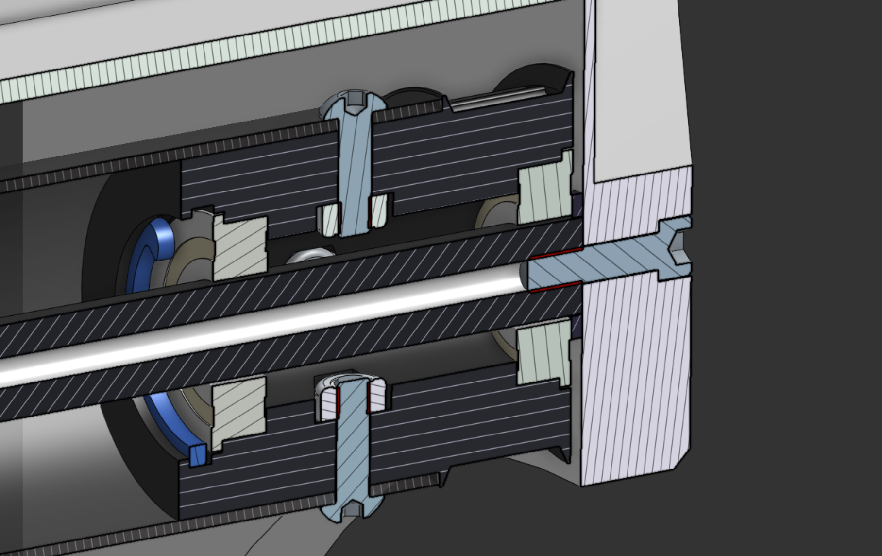
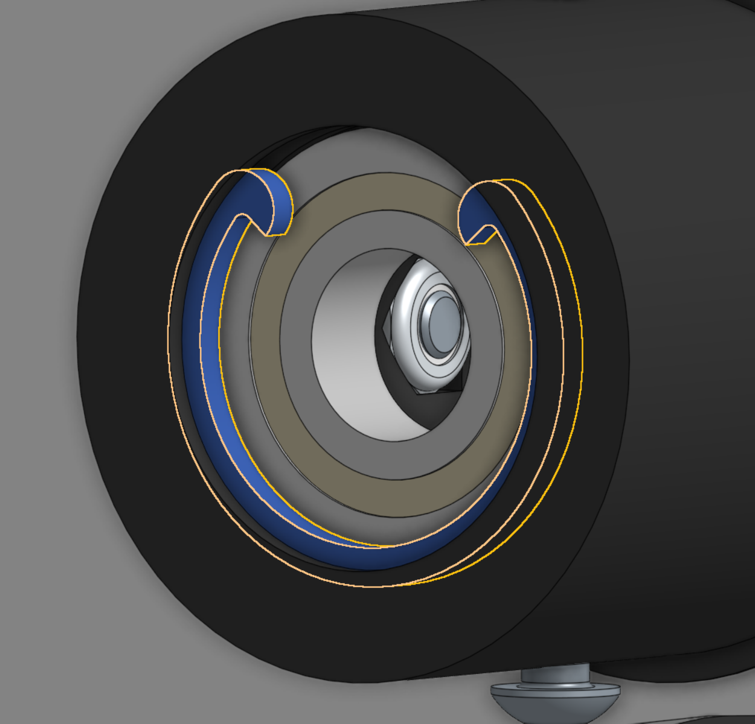
The main roller uses a dead-axle design: a ½″ hex shaft is fixed to the frame and does not rotate. Bearings inside 3D-printed stub hubs let the roller spin around it, and a 3D-printed snap ring holds each bearing in place — no machined groove or metal clip required. Because plastic hubs don’t hold machine-screw threads well, nut inserts fasten the polycarbonate roller tube to each hub.
Secondary rollers: the bolt is the axle
The secondary rollers use the same concept, simplified: a bolt serves as the dead axle, eliminating a separate shaft.